Methods for Detecting Load Break Switches
Load break switches are crucial components in electrical power systems, responsible for safely interrupting load currents under normal operating conditions. To ensure their reliable performance, a series of comprehensive detection methods are employed. These methods not only guarantee the proper functioning of the switches but also contribute to the overall stability and safety of the electrical network.
1. Visual Inspection
1.1 External Appearance Check
The most basic form of detection starts with a visual inspection of the load break switch's external appearance. This involves looking for any signs of physical damage, such as cracks, dents, or corrosion on the switch housing. Cracks in the housing can expose internal components to the environment, leading to potential insulation failures or short - circuits. Corrosion, especially in outdoor - installed switches, can weaken the structural integrity and affect the electrical connections. Additionally, any signs of overheating, like discoloration of the housing or melting of plastic parts, should be noted. Overheating may indicate problems with the current - carrying capacity or contact resistance within the switch.
1.2 Contact and Connection Inspection
Inspecting the contacts and connections is another vital aspect of visual inspection. The contacts should be examined for signs of pitting, burning, or uneven wear. Pitting and burning on the contacts can be caused by arcing during switching operations, which can increase the contact resistance and lead to further overheating. Uneven wear might suggest misalignment of the contacts, which can affect the proper closing and opening of the switch. Loose connections are also a major concern. Visual inspection can identify if any nuts, bolts, or terminals are not properly tightened. Loose connections can cause high - resistance joints, resulting in power losses, overheating, and potential electrical fires.
2. Electrical Testing
2.1 Insulation Resistance Test
An insulation resistance test is essential to determine the integrity of the switch's insulation system. A high - voltage insulation resistance tester, such as a megohmmeter, is used for this purpose. The test involves applying a specified DC voltage across the live parts of the switch and its grounded enclosure or other adjacent components. The measured insulation resistance value should be within the acceptable range specified by the manufacturer or relevant standards. A low insulation resistance value may indicate moisture ingress, insulation degradation, or damage to the insulating materials, which can pose a serious risk of electrical shock and short - circuits.
2.2 Contact Resistance Measurement
Contact resistance measurement helps assess the quality of the electrical connection between the contacts of the load break switch. A low - resistance ohmmeter or a micro - ohmmeter is used to measure the resistance between the closed contacts. The contact resistance should be kept as low as possible to minimize power losses and prevent overheating during normal operation. An increase in contact resistance can be a sign of contact wear, contamination, or improper contact force. Regular monitoring of contact resistance can help predict potential failures and schedule maintenance in a timely manner.
2.3 Dielectric Withstand Test
The dielectric withstand test, also known as the high - voltage test, is used to evaluate the switch's ability to withstand high - voltage stress without breaking down. In this test, a high - voltage AC or DC voltage, typically much higher than the rated voltage of the switch, is applied between the live parts and the grounded parts of the switch for a specified period, usually several seconds to a minute. If the switch passes the test, it means that its insulation system can handle the designed voltage stresses without arcing, flashover, or breakdown. Failure in this test indicates a serious insulation problem that needs immediate attention.
3. Mechanical Testing
3.1 Operating Force and Travel Measurement
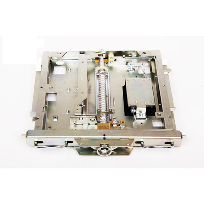
Measuring the operating force and travel of the load break switch's operating mechanism is important to ensure smooth and reliable operation. Specialized force - measuring devices, such as load cells, are used to measure the force required to open and close the switch. The operating travel, which is the distance the moving parts of the switch travel during operation, can be measured using displacement sensors. Deviations from the manufacturer - specified values for operating force and travel can indicate mechanical problems, such as stuck moving parts, worn - out springs, or improper adjustment of the operating mechanism.
3.2 Mechanical Life Test
The mechanical life test is a long - term test that evaluates the durability of the switch's mechanical components. During this test, the switch is repeatedly opened and closed a specified number of times, often in the thousands or even tens of thousands. After each cycle, the switch's performance is monitored for any signs of mechanical wear, such as excessive play in the moving parts, broken springs, or damaged linkages. The mechanical life test helps determine the expected service life of the switch and identify potential mechanical failures before they occur in actual operation.
4. Functional Testing
4.1 On - load Switching Test
The on - load switching test is carried out to verify that the load break switch can safely interrupt the rated load current. In this test, the switch is connected to a power source and a load, and then it is repeatedly opened and closed while carrying the rated current. The test monitors parameters such as the arc duration, arc voltage, and the ability of the switch to extinguish the arc without causing any damage to the switch or the connected equipment. This test is crucial as it simulates the actual operating conditions of the load break switch in a power system.
4.2 Overload and Short - Circuit Protection Test
To ensure the switch's ability to protect the electrical system under abnormal conditions, overload and short - circuit protection tests are conducted. For the overload test, the switch is subjected to a current higher than its rated value for a certain period. The switch should be able to carry the overload current without overheating or malfunctioning for a specified time as per the standards. In the short - circuit protection test, a simulated short - circuit current is applied to the switch. The switch should be able to quickly interrupt the short - circuit current and prevent damage to the electrical system.
In conclusion, a combination of visual inspection, electrical testing, mechanical testing, and functional testing is necessary to comprehensively assess the performance and reliability of load break switches. Regular and thorough detection using these methods helps in early detection of potential problems, ensuring the safe and efficient operation of electrical power systems.


.jpg)


